

The vents
Ventilation windows are 1,200 × 1,200 mm, or doubled to 1,200 × 2,400 mm where the calculation calls for more area. They are installed alternately along the ridge, so half the roof opens to one side and half to the other and the house can be vented on either wind direction without pressurising it.
-
Ridge vents Warm air rises to the ridge and leaves there, pulling cooler air in behind it. Up to five times as effective as side-wall openings of the same area.
-
Side-wall openings Air crosses at the level of the crop, and the hottest air — collected under the glass — has no way out.
Warm air rises and collects under the roof. An opening at the ridge lets it out and draws cooler air in behind it — with no fan and no energy input.
Each vent connection carries a lock, and a flexible seal runs along the threshold and both sides. The vents are locked against movement along the ridge — a vent that can creep will eventually find the pane next to it.

How much vent area a greenhouse needs
Vent area is usually expressed as a percentage of the floor area it serves, and the honest answer to how much is that it is a calculation with five inputs rather than a number.
What is being removed. Ventilation carries away the heat that arrives as sunlight and the moisture the crop transpires. Both scale with the light the house receives, so the requirement rises with latitude, with the share of clear-sky days, and with the crop's transpiration rate. A house in a cool, cloudy climate and a house in a hot, high-light one do not need the same roof.
How much of the vent is actually open. A vent's geometric area is not its ventilation area. The opening angle, the position along the ridge and the wind direction all change how much air a given opening moves. Ridge vents alternate along the roof — half opening one way, half the other — so the house vents on either wind direction instead of being pressurised by one.
-
Opening angle The drawn area is the vent's size, not its ventilation. How far it opens decides how much air it moves.
-
The leeward side Vents alternate along the ridge, so there is always an opening facing away from the wind — drawing air out instead of driving it in.
-
Screened Every insect net obstructs some of the opening, so the vent is sized for the screened condition, with the mesh already chosen.
The area on the drawing is the starting point. The air that actually leaves depends on these.
Whether it is screened. This is the one most often missed. Every net that stops an insect also obstructs air, so a vent sized on its open area and then screened at mesh 40 delivers less than the calculation assumed. The vent area is sized for the screened condition, with the mesh already chosen from the regional pest study — not sized open and screened afterwards. The screen itself is set out on the insect screening page.
The temperature difference driving it. Ridge ventilation is driven by buoyancy: warm air rises to the ridge and leaves, drawing cooler air in behind it. The driving force is the difference between inside and outside temperature and the height between the crop and the ridge. On a still, hot day with a small difference, ventilation alone will not hold the set point — which is where the cooling strategy begins, and why heating and cooling is designed with the vents rather than after them.
What is downstream of it. Energy screens, CO₂ dosing and a semi-closed cooling system all change the answer, because each of them either restricts the opening or changes what ventilation is being asked to do. CO₂ dosing in particular is in direct conflict with ventilation — dosed CO₂ leaves through an open vent — so the control strategy has to resolve the two.
The area is settled in the climate simulation against the site's thirty-year record. What this page fixes is the hardware: vents at 1,200 × 1,200 mm, doubled to 1,200 × 2,400 mm where the calculation calls for more, alternating along the ridge, on a drive that opens them by a controlled amount rather than fully or not at all.
Roof profiles and the ridge
The roof profile set is aluminium studs, Venlo arms and crown profiles with their connections. Where each pane is seated, a dedicated PVC profile keeps the glass off the aluminium, which makes breakage far less likely and closes the joint against air leakage.
The advantage of the Venlo arm in this system is that it goes in at the same time as the roof glass rather than after it, which removes a whole pass over the roof and is a real saving on a hectare.
The roof bars are fixed at the ridge by a torque-tight connection, which is why they stand 42.9 mm high there; below the ridge beam each bar seats into its stud. At the first and last bay, braces tie the top profile back to the studs — 3 mm wire with a size 6 brace — and a wind brace of Ø10 mm bar on a 50 × 50 × 2 mm profile stops the second stud from rotating.
The roof slope is 26 degrees.
The drive
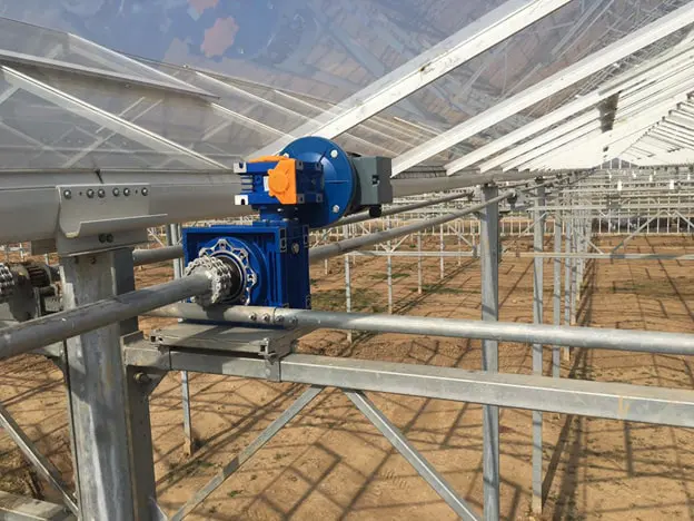
Opening is by rack and pinion. The push-pull rail mechanism is mounted on the truss and runs the length of the house.
The push-pull tubes are 26.7 mm steel, galvanised outside and zinc-coated within, carried on two bearing axes every 4.00 metres with PVC rollers. Each tube is clamped to a stabiliser block, and the block is what stops the tube rotating so that the rack cannot climb out of mesh — the single most common failure in a poorly detailed vent drive.
The vents themselves are pushed by two aluminium push-up bars with 1.22 mm tube. The drive axle is 42.4 × 2.5 mm, galvanised outside and zinc-coated inside, complete with bearing plate, and it runs beside the gutter.
The gear motor is 375 W at 3 rpm with two-way switching, supplied with its control equipment, electrical connections and wiring. Three revolutions per minute is deliberately slow: vents are moved in small increments many times a day by the climate computer, and speed at that duty buys nothing but wear.